BMW X5 (E70; 2007 – 2013) – fuse box diagram
Year of production: 2007, 2008, 2009, 2010, 2011, 2012, 2013
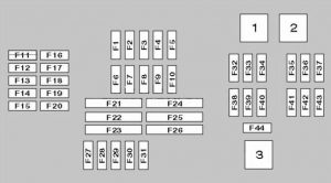
Instrument panel fuse box diagram
It is located under the glove compartment.

| № | A | Component |
|---|---|---|
| 1 | Suspension compressor motor relay | |
| 2 | Rear screen wiper relay | |
| 3 | Windscreen wiper motor relay | |
| F1 | 20A | – |
| F2 | 10A | Glove box locking motor |
| F3 | 7,5A | – |
| F4 | 10A | Engine control module (ECM) |
| F5 | 10A | – |
| F6 | 10A | – |
| F7 | 5A | – |
| F8 | 7,5A | – |
| F9 | 15A | Homs |
| F10 | 5A | – |
| F11 | 20A | – |
| F12 | 10A | Steering column function control module |
| F13 | 15A | Transmission control module (TCM) |
| F14 | 10A | |
| F15 | 10A | Transmission selector lever |
| F16 | 7,5A | Electric window switch |
| F17 | 7,5A | – |
| F18 | 7,5A | – |
| F19 | 5A | – |
| F20 | – | – |
| F21 | 30A | Heated rear window |
| F22 | – | – |
| F23 | 40A | – |
| F24 | 40A | Active steering |
| F25 | 30A | – |
| F26 | 30A | Head lamp washer pump |
| F27 | 15A | Central locking system |
| F28 | 15A | Central locking system |
| F29 | 40A | Rear electric windows |
| F30 | 30A | Central locking system |
| F31 | 40A | Rear electric windows |
| F32 | 40A | Suspension com pressor pump |
| F33 | 30A | – |
| F34 | 30A | – |
| F35 | 30A | Engine management |
| F36 | 30A | Engine management |
| F37 | 30A | Rear screen wiper motor |
| F33 | 30A | – |
| F39 | 40A | – |
| F40 | 30A | ABS control module |
| F41 | 7.5A | |
| F42 | 30A | Engine management |
| F43 | 30A | Engine management |
| F44 | 30A | Windscreen wiper motor |
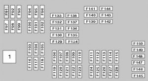
Luggage compartment

| № | A | Component |
|---|---|---|
| 1 | Circuit cut-off relay | |
| F91 | 30A/40A | – |
| F92 | 25A | Transfer box control module |
| F93 | 40A | – |
| F94 | 30A | (30A) Parking brake control module |
| F95 | 30A/40A | – |
| F96 | 40A | – |
| F97 | 20A | – |
| F98 | 15A/20A | – |
| F99 | 40A | (40A) Tail gate open/close control module |
| F100 | 20A | – |
| F101 | 30A | – |
| F102 | 30A | – |
| F103 | 30A | (30A) Audio unit output amplifier |
| F104 | – | – |
| F105 | 30A | – |
| F106 | 7,5A | – |
| F107 | 10A | – |
| F108 | 5A | – |
| F109 | 10A | Navigation system receiver |
| F110 | 7,5A | – |
| F111 | 20A | cigarette lighter (main ashtray socket) |
| F112 | 5A | – |
| F113 | 20A | cigarette lighter (center armrest console) |
| F114 | 5A | – |
| F115 | – | – |
| F116 | 20A | Trailer socket |
| F117 | 20A | – |
| F118 | 20A | – |
| F119 | 5A | Multimedia control module |
| F120 | 5A | Active suspension control module |
| F121 | 5A | Tailgate open/close control module |
| F122 | – | – |
| F123 | – | – |
| F124 | 5A | Fascia fuse box/relay plate |
| F125 | 5A | Transfer box control module |
| F126 | 5A | – |
| F127 | – | – |
| F128 | – | – |
| F129 | 5A | – |
| F130 | – | – |
| F131 | 5A | – |
| F132 | 7,5A | – |
| F133 | – | – |
| F134 | 5A | Steering column function control module |
| F135 | 20A | Tailgate open/close control module |
| F136 | 5A | – |
| F137 | 5A | Navigation system |
| F138 | – | – |
| F139 | 20A | – |
| F140 | 20A | Sea theater control module, left front |
| F141 | 20A | Seat heater control module, right front |
| F142 | 20A | Multimedia control module |
| F143 | 25A | Trailer control module |
| F144 | 5A | Trailer control module |
| F145 | 10A | Assisted door closing motor, right front |
| F146 | 10A | Assisted door closing motor, left front |
| F147 | 10A | Assisted door closing motor, left rear |
| F148 | 10A | Assisted door closing motor, right rear |
| F149 | 5A | Seat multifunction switch, left front |
| F150 | 5A | Seat multifunction switch, right front |
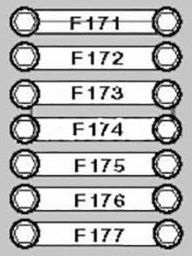
Fuses on the battery
Located on the battery in the luggage compartment, under the lining.

| № | Component |
|---|---|
| F171 | (100A) |
| F172 | (100A) |
| F173 | (250A) Dashboard fuse block |
| F174 | — |
| F175 | — |
| F176 | (80A) Valve lift control relay |
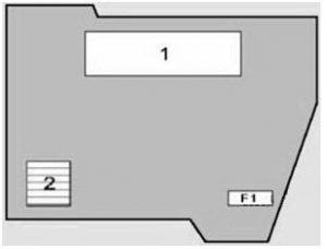
Block with relay and fuses in the engine compartment

| № | Component |
|---|---|
| 1 | Electronic block of the engine management |
| 2 | Valve lift control relay |
| F1 | (40A) Valve lift control relay |
Some relays can also be located under the lining, in the luggage compartment. For example, a compressor pump relay, a pneumatic suspension pump compressor relay.
The variants of the fuse layout, which you can find near the fuse box in the luggage compartment of your car.
| Symbol | Number |
| | 4, 15, 19, 123 |
| | |
| | 15, 24 |
| | 116, 143, 144 |
| | 6, 17, 18, 103, 107, 108, 109, 119, 127, 128, 132, 134, 142 |
| | 27, 28, 30, 124, 132, 135, 145, 146, 147, 148 |
| | 8, 106, 120 |
| | 13, 20, 92, 123, 125 |
| | 32, 107, 123 |
| | 23, 33, 34, 96, 124 |
| | 2, 19, 23, 33, 34, 96, 110, 124 |
| | 6, 142 |
| | 3, 5 |
| | 108, 114 |
| | 41 |
| | 9, 124 |
| | 16 |
| | 29, 31, 33, 34, 124 |
| | 100, 112, 139, 140, 141 |
| | 101, 102, 139, 140, 141, 149, 150 |
| OBD | 130, 131 |
| | 10, 94, 129 |
| | 1, 17, 18, 41, 98, 126 |
| | 4 |
| | 37, 44 |
| | 21 |
| | 124 |
| | 11, 12, 17, 91, 93, 95, 98 |
| | 5, 19, 23, 33, 34, 96, 114 |
| | 14 |
| | 18, 131 |
| | 6, 17, 19, 41, 126 |
| | 4 |
| | 97, 105, 122 |
 | 4, 7, 35, 36, 38, 42, 43 |
| | 137, 142 |
| | 10, 39 |
| | 99, 121 |
| | 6, 103, 109, 129, 142 |
| | 7 |
| | 44 |
| | 26 |
| | 5, 117 |
| | 110, 113 |
| | 1, 134 |
| | 111, 113, 115, 118 |
WARNING: Terminal and harness assignments for individual connectors will vary depending on vehicle equipment level, model, and market.
Source: https://www.autogenius.info/bmw-x5-e70-2007-2013-fuse-box-diagram/
Posted by: dougdougreismane0268837.blogspot.com